
 Español
  English


Even if they appear undamaged, a 125 kHz RFID card may still fail to be read. From a manufacturing perspective, the root cause may lie in the RFID chip itself or in a mismatch between the chip and the card’s radio frequency design.
When diagnosing faults in 125 kHz cards, we never draw conclusions based solely on replacing the reader or inspecting the card’s appearance. We conduct a comprehensive analysis of various chip-level characteristics: operating frequency, power-up behavior, modulation scheme, protocol compatibility, memory status, write-protect functionality, chip quality, and compatibility with the antenna and reader architecture.
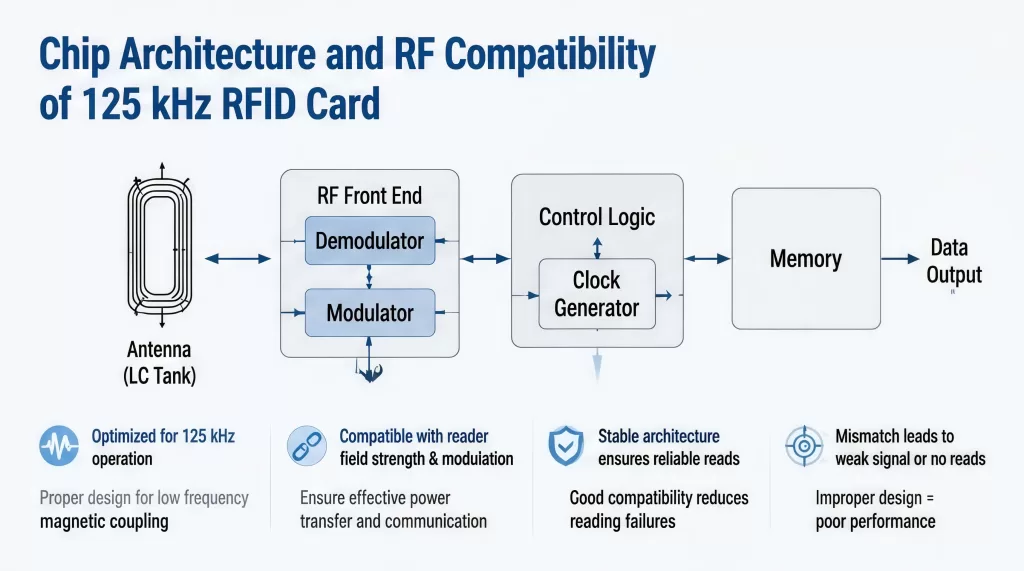
Chip Architecture and RF Compatibility of 125 kHz RFID Card
The primary chip-related factor is frequency compatibility.
125 kHz RFID cards are typically designed for the low-frequency (LF) RFID band, but “125 kHz” does not mean that all LF RFID chips have exactly the same RF characteristics. Some products operate within a frequency range centered around 125 kHz, while other LF RFID cards use closely related frequencies (such as 134.2 kHz) for specific applications.
We need to verify the selected chip’s actual operating frequency range, modulation scheme, data rate, communication protocol, and electrical characteristics. This is one of the most common causes of “card failure” during early prototype testing.
Before attributing the issue to the chip, we check the following:
- The specific chip model;
- Its supported frequency range;
- The reader’s operating frequency;
- The communication protocol;
- The card’s antenna characteristics.
Frequency mismatches can cause complete failure, as the chip may be unable to enter a valid operating state.
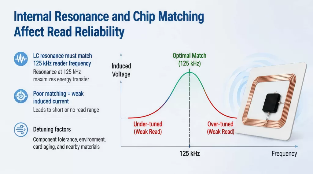
Internal Resonance and Chip Matching Affect Read Reliability
Some low-frequency RFID tag chips integrate resonance-circuit components internally. For example, certain 125 kHz identification chips have built-in resonance capacitors and require only an external coil to form an RF interface. This means that the chip’s internal electrical characteristics have become an integral part of the overall design for antenna resonance and power transmission.
This raises a practical manufacturing consideration: you cannot evaluate the chip independently of the antenna.
If the selected chip has different internal capacitance or matching requirements, the final card may exhibit issues such as resonance frequency deviation or reduced RF energy transmission efficiency. From a manufacturing perspective, you must revalidate RF performance when replacing a chip—simple software testing is not enough.
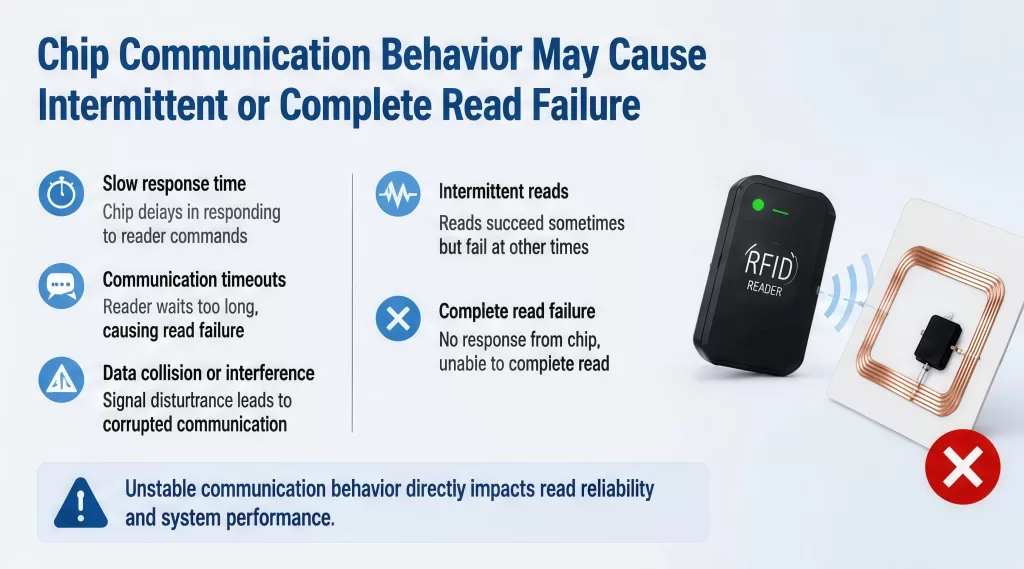
Chip Communication Behavior May Cause Intermittent or Complete Read Failure
After power-up, the chip must communicate with the card reader using a specific modulation scheme.
The card reader transmits information via an RF (radio frequency) field, while the transponder returns data by altering its electrical characteristics. Different series of low-frequency chips may use different modulation and encoding schemes. If the format the reader expects does not match the format the chip actually generates, the reader may detect RF signal activity but be unable to decode the card data.
This leads to an important diagnostic distinction:
Detecting an RF signal does not equate to successfully reading the card.
The reader may have sensed a response to the field but still be unable to identify the card.
When this situation occurs with a 125 kHz RFID card, we need to examine the chip’s modulation scheme, data encoding, data rate, start/stop behavior, protocol mode, and response timing.
Protocol Mismatches Can Make a Functional Chip Appear Defective
A particularly common misconception is that all 125 kHz cards use a uniform protocol.
However, this is not the case.
Some low-frequency transponders support proprietary protocols, while others support standardized or application-specific communication modes. Some are read-only, while others support read/write operations, password modes, authentication, or anti-collision features.
Take NXP’s HITAG series, for example: it includes a variety of devices, each with different protocols and memory configurations; this clearly shows that compatibility cannot be determined solely by the “125 kHz” frequency parameter.
Factors Affecting Chip Power Consumption, Data Integrity, and Memory Status in 125 kHz RFID Card
Insufficient radio frequency power may prevent the chip from completing initialization; passive 125 kHz chips must receive sufficient energy to start up and remain operational. If the available RF energy is close to the operating threshold, the chip may wake up successfully in one location but fail in another.
This is particularly important in the following scenarios:
- At a distance from the reader;
- At an unfavorable angle;
- Near metallic objects;
- Through thick casings;
- When used with readers that have weak field strength.
Although these conditions may stem from the antenna or the reader, the chip’s characteristics remain critical, as different chips have varying power consumption requirements and RF sensitivity. For this reason, we evaluate the system’s power margin rather than simply whether the chip functions under ideal laboratory conditions. A well-designed system should provide sufficient margin between the normal operating point and the chip’s minimum power requirement.
Chip Quality and Manufacturing Variations in 125 kHz RFID Card
Even when the correct chip series is selected, manufacturing variations can still affect performance. Semiconductor devices are manufactured within specified tolerance ranges. If a card’s RF system is already operating at the limit, component variations may cause the performance of some cards to fall outside acceptable limits.
This can lead to a common production issue:
The vast majority of cards function normally, but a small number perform poorly.
When this happens, the problem may not lie with the reader design itself; rather, the manufacturing process may have exposed insufficient RF margin. Therefore, professional smart card manufacturers conduct sampling tests and batch-level validation, rather than simply verifying a single card under ideal conditions.
How to Distinguish Between Chip Issues and Antenna or Reader Issues?
A key principle in troubleshooting 125 kHz RFID systems is that not all read failures stem from chip malfunctions. The chip is part of the radio frequency (RF) system, and its performance depends on several factors, including the antenna, resonant circuit, reader electronics, card structure, and the surrounding environment.
H3: Using a Known-Good Reference Card
The quickest preliminary test is usually a side-by-side comparison.
Use:
- A reader confirmed to be functioning properly;
- A reference card from the same chip series confirmed to be functioning properly;
- The customer’s card;
- The same reading position.
If the reference card reads normally but the customer’s card consistently fails to read on the same reader, focus on troubleshooting the card itself.
Compare Behavior at the Chip Level, Not Just Reading Distance
While read range is certainly important, it alone is insufficient to diagnose the problem. Even if a card’s read range falls within an acceptable range, issues such as data errors, encoding errors, authentication failures, or unstable protocol responses may still exist.
Therefore, we recommend testing at multiple levels, including RF activation, chip identification, data decoding, and memory access. This layered testing approach helps pinpoint where communication breaks down.
Identify the Problem and Troubleshoot Step by Step
Failed reads of 125 kHz RFID cards are not always caused by card damage or weak reader signals. The chip plays a critical role in whether the card powers up normally, communicates according to the expected protocol, transmits data in the correct format, and completes the required storage or authentication operations.
The most important chip-related factors include:
- Frequency and RF compatibility
- Power-up behavior
- Modulation and protocol compatibility
- Memory architecture
- Data integrity functions
- Protection and application states
- Chip-to-antenna matching
- Manufacturing consistency
Therefore, the most reliable way to prevent 125 kHz card read failures is to evaluate the chip as part of a complete RFID system.
The core principle is simple: when a 125 kHz RFID card cannot be read, first identify where the interruption occurred in the communication chain before replacing any components. This approach helps you troubleshoot issues faster and make more accurate decisions.